Tip 1: What is Rotational Motion
Tip 1: What is Rotational Motion
Rotational movements are performed duringwarm-up or physical exercise, with the circular rotation of the arms and legs. These movements are done, for example, in a complex of exercises aimed at strengthening joints.

Tip 2: What is a spindle
Cylindrical parts that can rotate inboth sides, called the spindle. Usually, they are used in machine tools and lathes to secure the workpiece, or as a separate element of the turning device

The spindle is a spindle - Spindel. Indeed, the shafts, which are installed in modern equipment for the transmission of torque, are very reminiscent of a spindle rotating around its own axis. Such a shaft is used to a greater degree in metal working on metal-cutting machines.
Turning spindles
On the front head of the lathe setThe spindle at the end of which the collet is attached, which serves to clamp the workpiece to be machined. At the back of the head of the lathe, a spindle is installed to secure the tool. Both spindles have rotational movement, both in the left and in the right side. In the spindle of the tailstock of the lathe there is a conical hole in which the cutting tool is fixed. In modern metalworking machines, spindles are installed with the ability to fasten one or two cutting tools. Spindles are manufactured with increased accuracy, given that the rotational motion requires precision to uniform workpiece machining. A caliper with a spindle of the tailstock of a lathe is fed to the rotating spindle with the clamped workpiece. This workpiece requires increased precision in the manufacture and installation of shafts, so the spindles are mounted on sliding or rolling bearings with a high class of accuracy.Manufacture of a shaft
To install modern spindles, use theprecision ceramic or metal bearings that do not require additional lubrication. If the technology of the workpiece requires the replacement of various cutting tools, a spindle with quick-change tool holders is installed on the machine tool, and a spindle with automatic tool changing is installed on the most modern metal-cutting machines. or a drilling group of machines, as well as on aggregate and boring machines, the spindle has a manual or mechanical drive with which the shaft is installed It is obvious that the device, which is intended for long rotation with loads, requires special conditions and materials of manufacture. Thus, modern shafts are made of refractory material with a high coefficient of resistance. In terms of speed characteristics, the spindles can be high-speed or low-speed, and by type of operation they can be cooled by either liquid or air. High-speed shafts, which are used for grinding, are able to transmit a torque of 60,000 rpm, low-speed shafts up to 12,000.Tip 3: How to assemble a magnetic motor
Not all electric motors at work makerotary motion. There are among them linear, reciprocating movements. It can be converted into rotational by means of a crank-and-rod mechanism, as in an internal combustion engine.

You will need
- - contactor;
- - plexiglas;
- - a capacitor, a light bulb, a diode;
- - wires;
- - bolts with nuts;
- - a screwdriver and a wrench;
- - soldering iron;
- - Drill;
- - 24-volt power supply.
Instructions
1
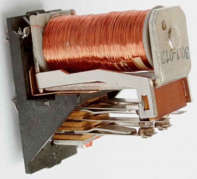
As a basis for a magnetic motor,creating a reciprocating motion, take the old contactor. Its coil should be rated for 24 V DC. Find a pair of normally closed contacts near the appliance. These are the contacts that are closed when the power is de-energized and is closed when the relay trips. Connect these contacts in series with the coil.
2
In parallel with the winding, attach in a straight linepolarity series circuit, which includes an electrolytic capacitor with a capacity of about 2000 μF and a bulb of 24 V, 90 mA (commutator). This is a delay circuit that causes the magnetic motor to work not too fast. Without it, the frequency of switching on and off the contactor would be determined only by the inertia of its mechanism.
3
Also, parallel the winding, but for thisonce not in a straight line, but in a reverse polarity, a diode of the type 1N4007. It will protect it bursts of self-induction not only contacts and elements of the time-setting chain, but also the experimenter himself. But completely rely on it is not necessary, because it can at any time break down.
4
Feed the assembled structure through0.5 amp fuse, observing the polarity, a constant supply voltage equal to 24 V. If everything is assembled correctly, the contactor should begin to periodically retract and release. De-energize the magnetic motor, and then glue a thin wooden rod to the solenoid rod so that the stem itself does not stick to the body.
5
Perpendicular to the rod, place the crankeda shaft bent from a paper clip. Secure it in a U-shaped corner, which is placed on a common L-shaped base with a contactor. The rod and the crankshaft are connected with each other by a connecting rod, also made of a paper clip. At both ends of the connecting rod there must be eyelets, and, the one that is facing the rod, fix on the last clerical clip, inserted not completely. On one side, attach a flywheel to the crankshaft - a plastic disc about 30 mm in diameter.
6
By feeding power to the magnetic motor, immediatelyuntwist a flywheel. It will start to rotate in the direction in which you push it. If this does not happen, experiment with various combinations of device element sizes. Disconnect power before making any changes to the design.